XIAMEN ACEY NEW ENERGY TECHNOLOGY CO., LTD.
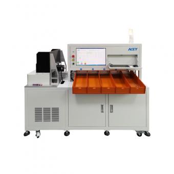
![$this->product_detail['product_name']](/uploadfile/category/21ba821835cda2ca9839bd228e6114af.jpg)


Brand:
ACEYItem No.:
ACEY-BP32-500A800ACompliance:
CE CertifiedWarranty:
One-year warranty with lifetime supportOrder(Moq):
1Payment:
T/TProduct Origin:
ChinaLead Time:
7-35 days1-32 Series 500A Charge 800A Discharge Battery Management System BMS Tester
Product Description
ACEY-BP32-500A800A BMS Tester is a high-precision testing system designed for comprehensive performance evaluation of Battery Management Systems (BMS). It supports a wide range of tests including overcharge and overdischarge protection and recovery, overcurrent (charge/discharge), internal resistance, self-consumption, short-circuit protection, protection delay times, as well as balancing current and voltage. Compatible with lithium ternary, lithium iron phosphate (LiFePO₄), and lithium cobalt oxide batteries, the system features flexible test mode switching to meet diverse application needs. With the capability to handle up to 500A charging and 800A discharging currents, it is ideal for EV, e-forklift, and large-scale ESS manufacturers. The tester operates via a computer connection using a standard RS-232 interface and requires only basic PC configuration (typically Windows XP), ensuring easy integration and user-friendly operation.
Parameter
1. Input power requirements: 180 ~ 240V 50/60HZ, power: 5000W
2. The equipment access to the power requirements of the domestic use of 220V/50HZ alternating current, allow fluctuations in the range of 10% or less.
3. Charging and discharging voltage: 5000mV ~ 160,000mV
4. The equipment can be used to detect and set the voltage range when charging or discharging.
5. Current accuracy: ±(0.1%FS+0.1%RD)
6. When the device detects or sets the current, the error range, i.e. 0.1% of the full scale plus 0.1% of the reading error
7. Voltage accuracy: ± (0.1%FS+0.1%RD)
8. Equipment in the detection or setting voltage, the error range, that is, 0.1% of the full scale plus reading error 0.1%.
9. Current resolution: 1mA, the smallest unit used by the device when detecting or setting current.
10. Voltage resolution: 1mV, the smallest unit used when the device detects or sets the voltage.
11. Cycle: cycle times:1~9999 times
12. Using the programming, the number of times the device carries out an uninterrupted cycle of the various indicators of the protection board.
13. Log tracking
14. With log function, including testing the entire process of operation records, exception records, can be used to test the process of tracing.
15. Data processing, man-machine interface
16. Test data is saved in EXCEL file.
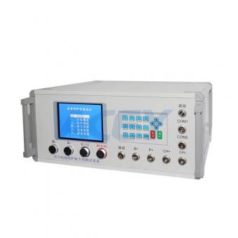
17. The RS232 interface is used for the interface between the device and the upper computer, which can ensure the stability and real-time data acquisition.
18. Accuracy calibration / software calibration
19 with a sweep start function
20.MES system connection
Test Functions
No.
Function
Setting range
Testing accuracy
Unit
1
Single section self-consumption
0--500
±0.1
uA
2
Self-consumption
0--5000
±1
uA
3
Overcharge protection voltage
500--5000
±1
mV
4
Overcharge protection release voltage
500--5000
±1
mV
5
Overcharge protection delay time
0--10000
±1
mS
6
Over-discharge protection voltage
500--5000
±1
mV
7
Over-discharge protection release voltage
500--5000
±1
mV
8
Overcharge voltage protection delay time
0--10000
±1
mS
9
Overcharge current protection value
0.1--500
±0.01
A
10
Overcharge current protection delay time
0--20000
±1
mS
11
Overcharge current protection value
0.1--800
±0.01
A
12
Over discharge current protection delay time
0.1--20000
±1
mS
13
Equalizing opening voltage
500--5000
±1
mV
14
Equalizing Current
1--500
±1
mA
15
Charging Aging Current
0.1--200
±0.01
A
16
Discharge Aging Current
0.1--200
±0.01
A
17
Charging aging time
0--30
±1
S
18
Discharge current aging time
0--60
±1
S
19
Single section self-consumption difference
0-500
±0.1
uA
20
Resistance
0-999
±1
mΏ
21
Short circuit protection time
0--5000
±1
uS
22
Charging aging voltage
500--5000
±1
mV
23
Single discharge aging voltage
500--5000
±1
mV
24
Open circuit voltage
102000
±1
mV
25
Number of voltage simulations
32
0
PCS
Other technical parameters
| Item | Parameter Description |
| Consumption Current Measurement Range | 1 ~ 5000uA |
| Consumption current resolution | 0.1uA |
| Resistance | AC internal resistance:0-999mr |
| Protection time resolution: | overcurrent protection time: 0-999ms; short circuit protection time: 0-999us |
| 1 channel signal voltage output: | 500~5000mV |
| AD/DA bit | AD: 16bit DA: 16bit |
| Discharge mode | CC mode |
| 32 analog cores | Input/output 500~5000mV, voltage accuracy ±0.1% |
| Communication rate | 2-way SBS communication, communication rate 10~100Kbps |
| Other | One way voltage sampling, 0~5000mV, accuracy:±0.1% |
| Protection function | Global protection parameters (including reverse connection protection, voltage lower limit protection, voltage upper limit protection, current upper limit protection), CC charging protection parameters (abnormal voltage trend protection, abnormal charging current fluctuation protection, abnormal voltage fluctuation protection), CC discharge protection parameters (including abnormal voltage trend protection, abnormal discharge current fluctuation protection, abnormal voltage fluctuation protection) |
| Communication | The interface of the device adopts RS232/DB9 interface, and the communication rate is 38400, which can ensure the stability and real-time data acquisition. All communication ports of the device are isolated and have lightning protection design. |
| Circuit structure | Modular structure, available spare parts, spare parts for timely replacement and maintenance. |
| Equipment organization | Split cabinet structure |
| Safety level | Conforms to EN60950 and GB4943 requirements. |
| Noise | Test noise according to IEC62040-3 method, noise less than 70dBA. |
| The sound level meter used should meet the requirements of IEC804 Type I, and the accuracy should be better than ±0.5dB. | |
| Protection grade | IP20 |
| Cabinet color | Gray-white |
| Cabinet color | Gray-white |
| Lightning protection | Reach the 2-pole lightning protection requirement of GB17626. |
| Cooling | Forced air cooling, air outlet and air inlet to retain at least 20cm of space |
| Starting pulse voltage | The maximum allowable pulse voltage at the moment of equipment testing and starting the process is ≤ (set number of test strings * set voltage of single unit)*110%, T≤500uS; |
| Starting pulse current | The maximum allowable pulse current at the moment of equipment testing and starting overcurrent testing process is ≤ (set number of test strings * set single-unit voltage * 110%, T ≤ 500uS); T ≤ 1mS; |
| Wiring method | Adopt reliable spring crimping method, flexible disassembly and replacement. |
Product Display


 1-24 Series 40A Charge 120A Discharge High Precision Lithium Battery Protection Board BMS Tester
ACEY-BMS24-120 can detect the function of the lithium battery protection board and various performance indicators, facilitate the debugging and development of samples, and provide a set of standards for rapid detection for R&D personnel.
 24 Series 40A Charge 200A Discharge Battery Management System Protection Board BMS Tester
Battery protection board tester is used to test the performance and functionality of BMS. By using a battery protection board tester, manufacturers and users can ensure the quality and reliability of the protection boards, reducing the risk of battery failures and potential safety hazards.
 1-24 Series 200A Charge 300A Discharge BMS Tester Lithium Battery Protection Board Tester
ACEY-BP24-200A300A is a powerful testing device that can accurately measure and analyze various parameters of BMS to ensure the normal operation and efficiency of the battery management system.
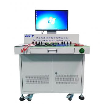
 1-32 Series 200A Charge 200A Discharge Battery Management System Tester BMS Testing Machine
ACEY-BP32-200A200A BMS Tester is a professional testing equipment designed for verifying the performance and reliability of Battery Management Systems (BMS) used in lithium battery packs. It provides accurate simulation of charging, discharging, and protection conditions, ensuring the BMS operates safely and effectively in real-world applications.
 1-24 Series 50A Charge 120A Discharge Bms Tester Machine
ACEY-BP24-50A120A BMS tester is used to test multiple functions of the protection board, including overcharge protection, overcharge recovery, overdischarge protection, overdischarge recovery, overcurrent protection (overcharge current and overdischarge current), internal resistance, self-consumption, short circuit protection, overcharge protection time, overcurrent protection time, overdischarge protection Time, balance current, balance voltage etc.
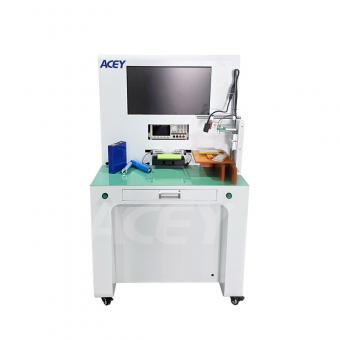 Manual Battery OCV And Internal Resistance Tester For Cylindrical/Prismatic/Pouch Cells
ACEY-MS03 is a testing machine specially designed for OCV and internal resistance testing of cylindrical, prismatic, and pouch batteries. It allows manual operation on a single unit to complete testing and grading for multiple battery types.
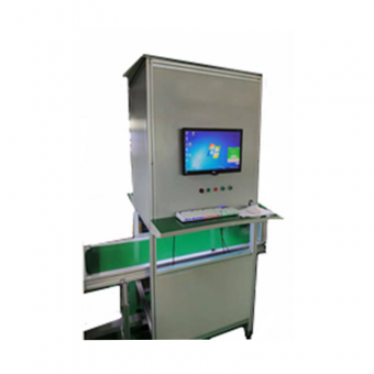 Cylindrical Lithium Battery Pack CCD Tester
CCD camera tester positive and negative testing Cylindrical Battery before welding welding testing equipment
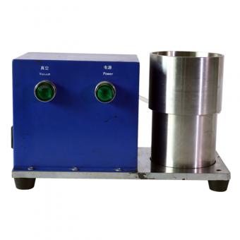 Small 0.5L Magnetic De-ironing Filtration System for Battery Electrode Slurry
This filter device is mainly applied to a special filter designed for laboratory samples to filter out various hard particles with a particle size of not less than 124 microns in the slurry. The whole machine has beautiful design and is flexible and convenient to use.
703, 7F, Zhonghengji Building, No.223, Qishan North Road, Huli District, Xiamen, Fujian, China
Email : allen@xmacey.com
Tel : +8618950009155
Whatsapp : +8618950009155