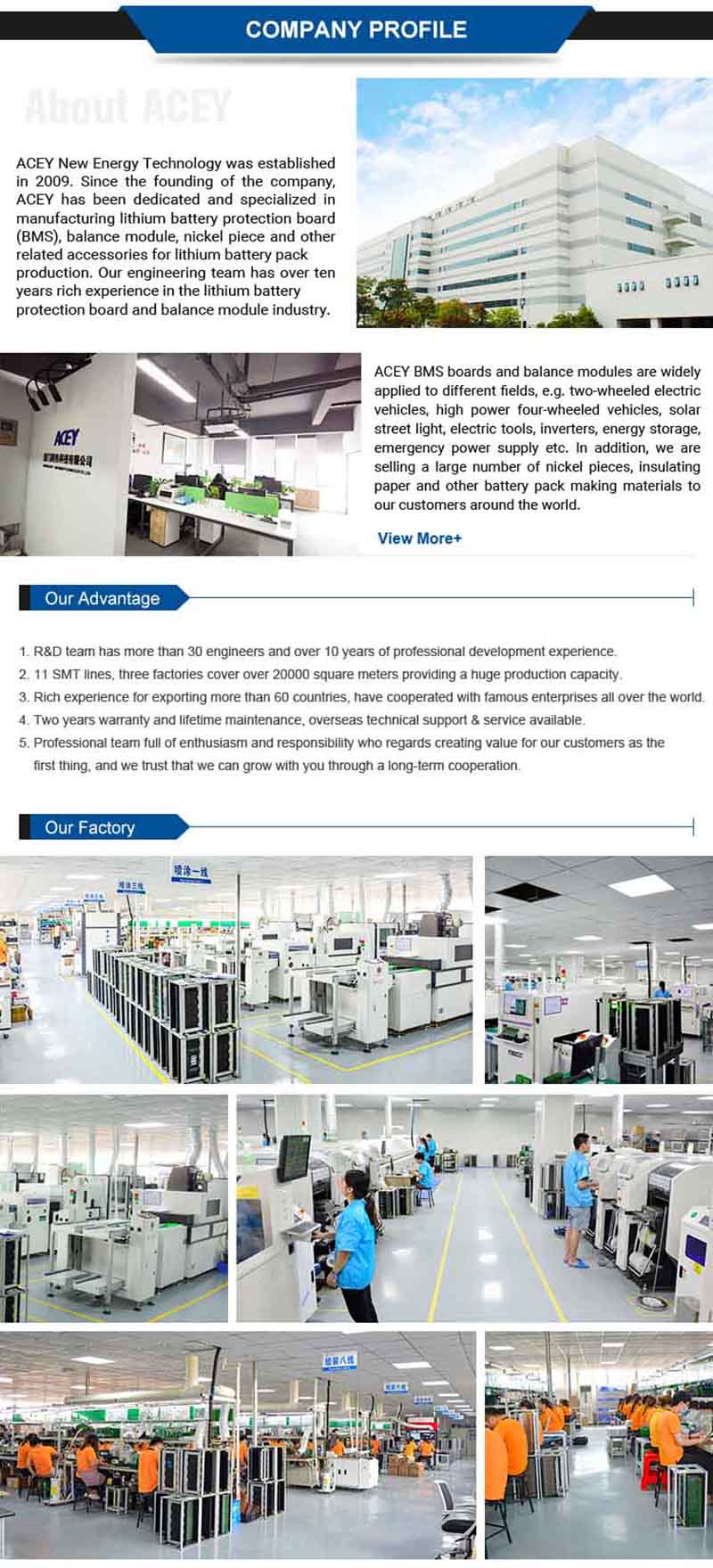
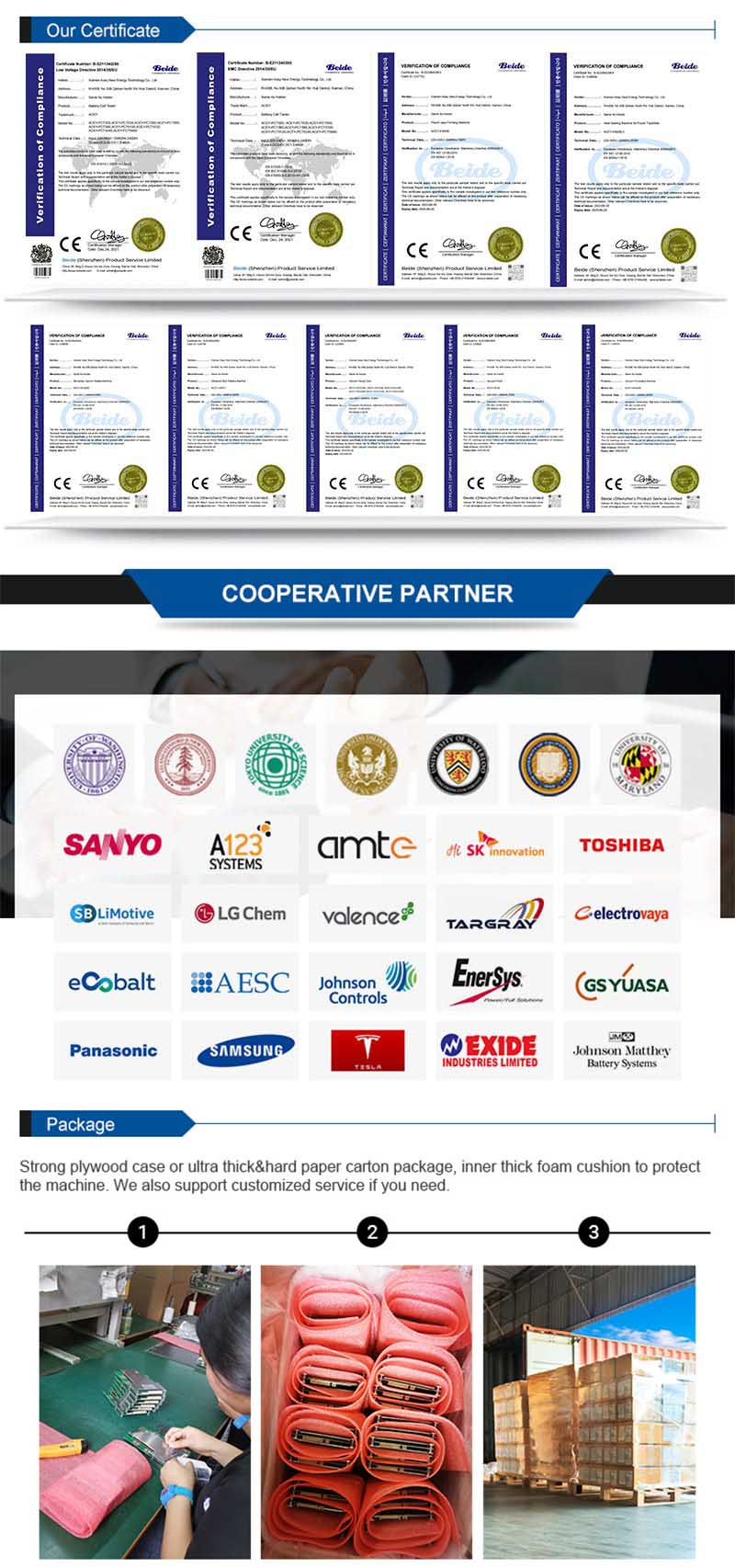
XIAMEN ACEY NEW ENERGY TECHNOLOGY CO., LTD.

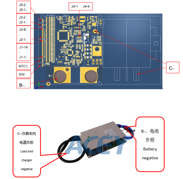
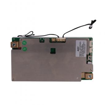
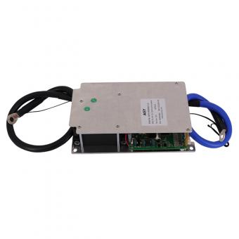
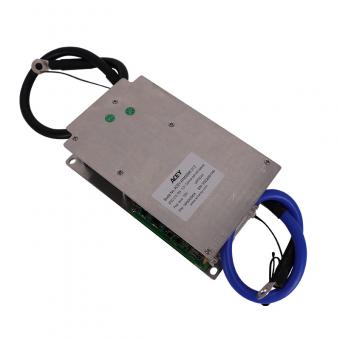
ACEY-SP10S020 is specially designed for 8 strings battery packs can be applied to lithium batteries with different chemical properties, such as lithium ion, lithium polymer, lithium iron phosphate, etc.
Brand:
ACEYItem No.:
ACEY-SP10S020Compliance:
CE CertifiedWarranty:
One Year warranty with lifetime supportOrder(Moq):
Payment:
T/TProduct Origin:
ChinaLead Time:
7days8s 10s 36v 30A Li-ion Pcm Smart Bms With UART RS485 communication
Product Introduction
ACEY-SP10S020 is specially designed for 8 strings battery packs can be applied to lithium batteries with different chemical properties, such as lithium ion, lithium polymer, lithium iron phosphate, etc.
The whole system adopts the front-end acquisition chip + MCU of TI (Texas Instruments), and some parameters can be flexibly adjusted through the host computer according to customer needs.
Features
8~10 series battery protection in series.
The cells are intelligently balanced, and the balanced turn-on voltage and differential pressure can be flexibly adjusted through the host computer. Optional charge equalization or static equalization.
Integrated hardware protection functions such as overvoltage, undervoltage, overcurrent and short circuit.
Multiple working modes, when the protection board is in static state, it can delay to go to sleep to achieve the purpose of reducing power consumption.
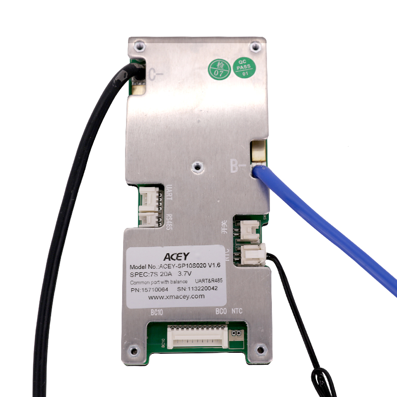
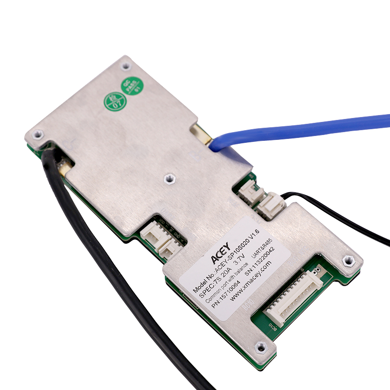
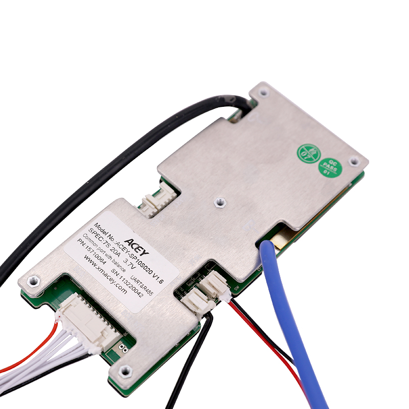
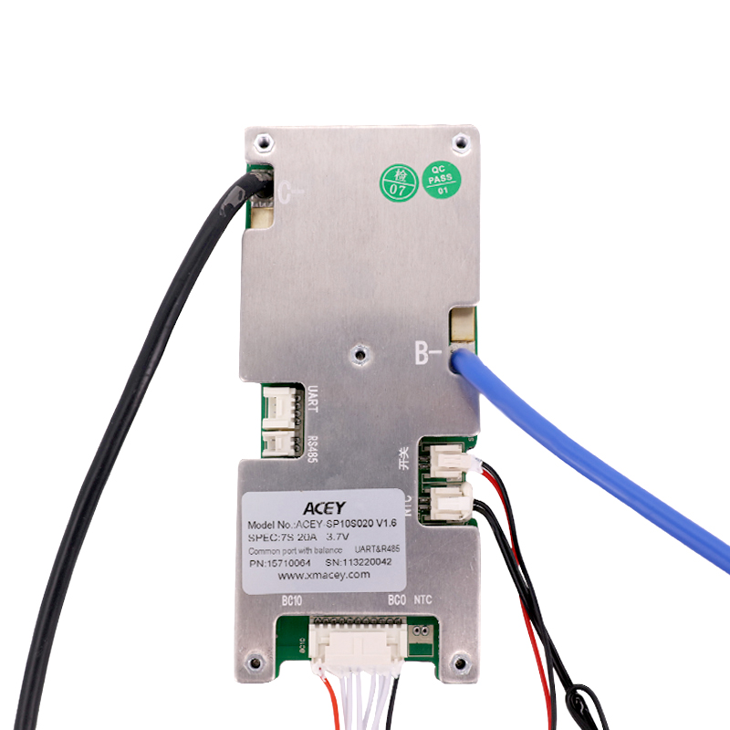
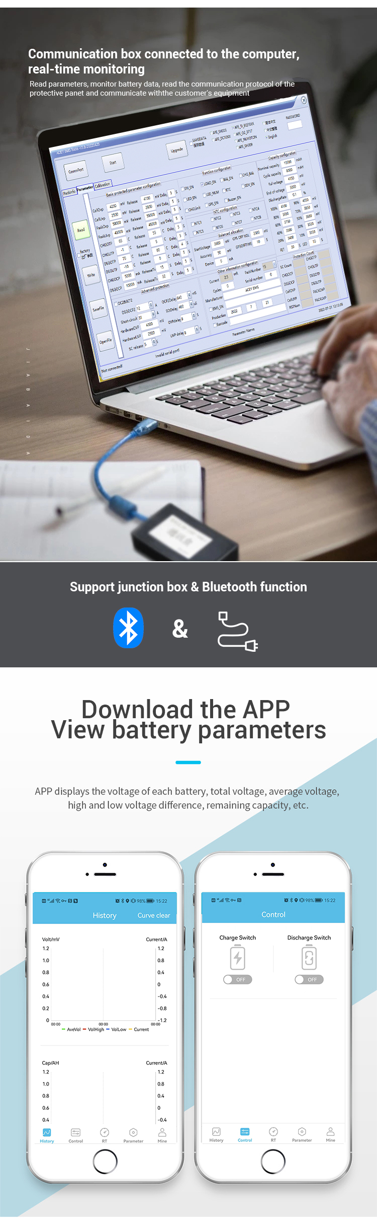
It comes with two communication ports, which can read data such as voltage, current, SOC, temperature, and protection status.
UART (TTL level) can be connected to external Bluetooth, computer and non-battery powered devices.
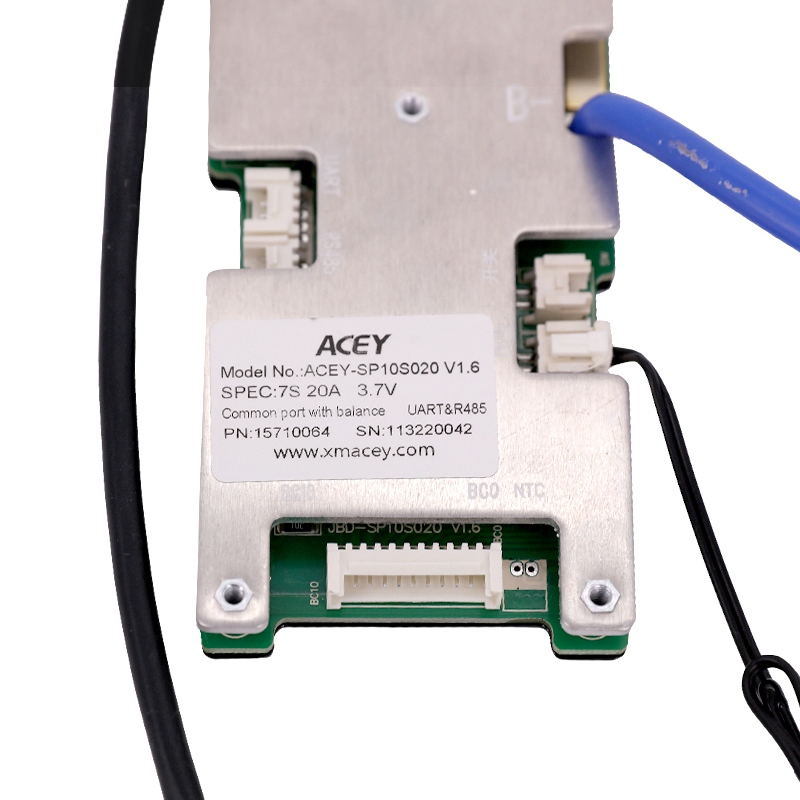
With 3 temperature detection probes, the default one detects the internal temperature of the protection board, and the rest are placed where the temperature needs to be detected according to customer needs.
Support 485 communication;
Reserved Battery total voltage detection function;
Basic parameters
| Cell Specifications | 8stringLithium ironBattery |
| Interface Type | Charge and discharge at the same port |
| Recommended charging voltage | 28.8V |
| Operating voltage range | 17.6V~30V |
| Continuous charge current | ≤35A |
| Continuous discharge current | ≤35A |
| Running power consumption | ≤20mA |
| Sleep power consumption | ≤250uA |
| Protection board internal resistance | In-board charge and discharge MOSIn the case of both conduction, B-Solder joint to output solder joint internal resistance≤10mR |
| Operating temperature | -30°C~75°C |
| Protective plate size | 140±0.5mm*60±0.5mm *11±1mm(length Width Height) |
Electrical Characteristics (The test needs to be carried out in a room with a temperature of 25 ± 2 C and a relative humidity of 65 +/- 20 %)
| Features | project | Specification | unit | ||
| minimum | Typical value | maximum value | |||
| Monomer overpressureProtect | PasspressureProtection voltage | 3.7 | 3.75 | 3.8 | V |
| Overcharge protection delay time | 1000 | 2000 | 3000 | mS | |
| Overcharge protectionrecoverVoltage | 3.55 | 3.6 | 3.65 | V | |
| Monomer overdischargeProtect | Over discharge protection voltage | 2.1 | 2.2 | 2.3 | V |
| Over-discharge protection delay time | 1000 | 2000 | 3000 | mS | |
| Over discharge protectionrecoverVoltage | 2.6 | 2.7 | 2.8 | V | |
| PassputProtect recovery conditions | Disconnect the load or resume charging | ||||
| ChargeOvercurrent Protection | Charge overcurrent protection value | 35 | 45 | 55 | A |
| Charge overcurrent delay | 8 | 10 | 12 | S | |
| Charge Overcurrent Release Condition | Automatic recovery after a delay of 32S | ||||
| dischargeOvercurrent Protection | primary dischargeOvercurrent protection current | 35 | 45 | 55 | A |
| primary dischargeovercurrent1protection delay | 8 | 10 | 12 | S | |
| secondary dischargePassflowProtection current value | 90 | 110 | 130 | A | |
| secondary dischargeovercurrent2protection delay | 150 | 320 | 500 | mS | |
| dischargeOvercurrent Protection Recovery Conditions | Automatic recovery after a delay of 32S | ||||
| Short circuit protection | Short circuit protection circuit | 300 | 440 | 600 | A |
| Short circuit protection delay time | - | 400 | 800 | uS | |
| Short circuit protection recovery | Delay 5 after disconnecting the loadS recovery. | ||||
| Short circuit description | Short-circuit description: The short-circuit current is less than the minimum value or higher than the maximum value, which may cause the short-circuit protection to fail, and the short-circuit current exceeds1000A, short-circuit protection is not guaranteed, and short-circuit protection testing is not recommended. | ||||
|
Discharge high temperature protection (external) |
temperature protection value | 72 | 75 | 78 | °C |
| Temperature protection release value | 62 | 65 | 68 | °C | |
|
Discharge low temperature protection (external) |
temperature protection value | -25 | -20 | -15 | °C |
| Temperature protection release value | -15 | -10 | -5 | °C | |
|
Charging high temperature protection (external) |
temperature protection value | 62 | 65 | 68 | °C |
| Temperature protection release value | 52 | 55 | 58 | °C | |
|
Charging low temperature protection (external) |
temperature protection value | -20 | -15 | -10 | °C |
| Temperature protection release value | -15 | -10 | -5 | °C | |
| FET discharge high temperature protection | temperature protection value | 85 | 90 | 95 | °C |
| protect(Built-in curing) | Temperature protection release value | 65 | 70 | 75 | °C |
| Equalization function | Turn-on voltage | 3.35 | 3.4 | 3.45 | V |
| Open differential pressure | 15 | mV | |||
| Balance current | 30 | 80 | mA | ||
| Balanced way | Charge equalization | ||||
| Balance type | time-sharing\Pulse equalization | ||||
| - | - | ||||
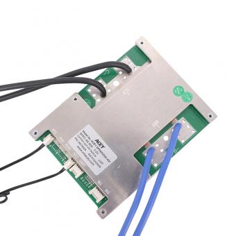
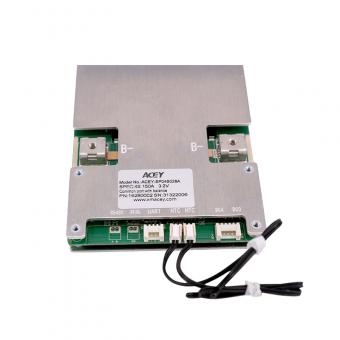
Product Display


 4s Lifepo4 12v 200a Smart Bms With UART/RS485 And Heating Function
ACEY-SP04S034 is a software protection board scheme specially designed for 3~4 strings of lithium battery packs.
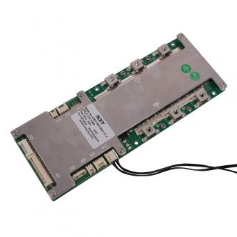
 7S-20S 200A 300A 3.2V Lifepo4 Smart BMS With UART RS485
ACEY-AP20S006-LFP is a software protection board scheme specially designed for 7~20 strings of lithium battery packs.
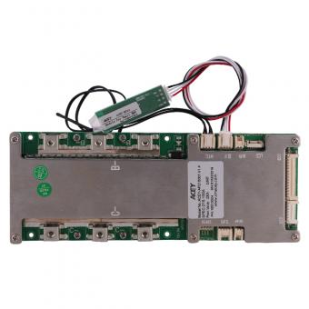
 7S 20S 3.7V 200A 300A NMC Smart BMS With Balance UART RS485
【ACEY-AP20S006-NMC】7~20 strings of Lithium Iron Battery
 6S-21S 3.2V 100A 200A Software Lifepo4 Smart BMS With UART
ACEY-AP21S001 is specially designed for 6~21 strings of lithium battery packs.
 21S 3.7V 100A 200A NMC Smart BMS Manufacturers With UART
【ACEY-AP21S001】6s-21s 100A~200A NMC Smart BMS with UART.
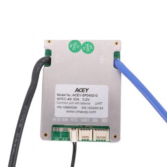 4S 30A Smart Wireless Lifepo4 Bms With UART RS485 Communication
ACEY-SP04S010 is an intelligent protection board scheme specially designed for 3 ~ 4 series battery packs of power tools, 12V starting power supply, medical batteries and other products.
 4S 80A 3.2v Lifepo4 Smart Bms 12v Protection Board with UART and RS485
【ACEY-SP04S020】4S 80A 12v lifepo4 battery pack smart bms protection board with UART and RS485 for electric motor
 150a 12v 4s Protection Circuit Board With UART and RS485 for Lifepo4 Battery
【ACEY-SP04S028A】4S 150A 12V battery management system smart bms for lifepo4 battery with UART and RS485.
703, 7F, Zhonghengji Building, No.223, Qishan North Road, Huli District, Xiamen, Fujian, China
Email : allen@xmacey.com
Tel : +8618950009155
Whatsapp : +8618950009155