XIAMEN ACEY NEW ENERGY TECHNOLOGY CO., LTD.

ACEY-SP25S003 is designed for 7-25 series battery packs of start-up battery and electric energy storage products.The maximum continuous discharge current can reach 100A.
Brand:
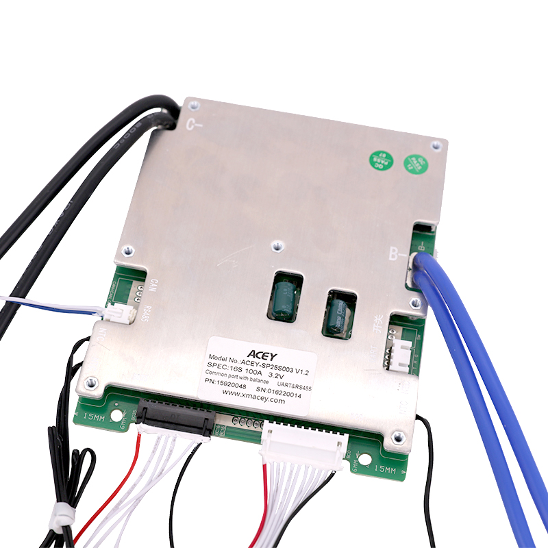
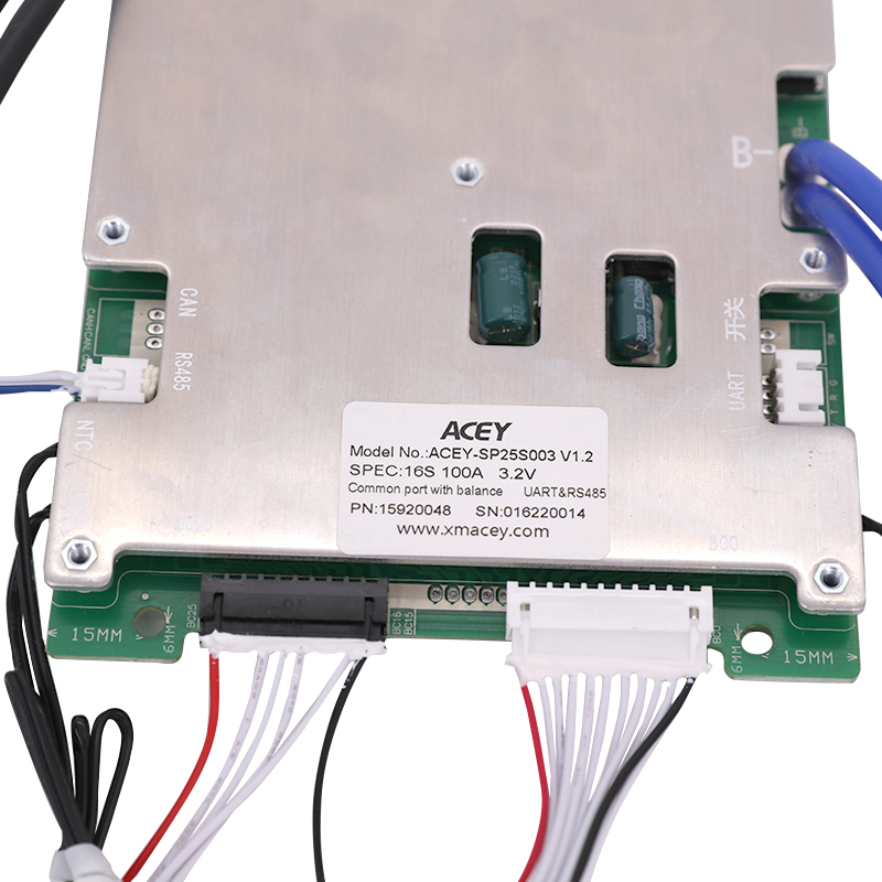
ACEYItem No.:
ACEY-SP25S003Compliance:
CE CertifiedWarranty:
One Year warranty with lifetime supportOrder(Moq):
Payment:
T/TProduct Origin:
ChinaLead Time:
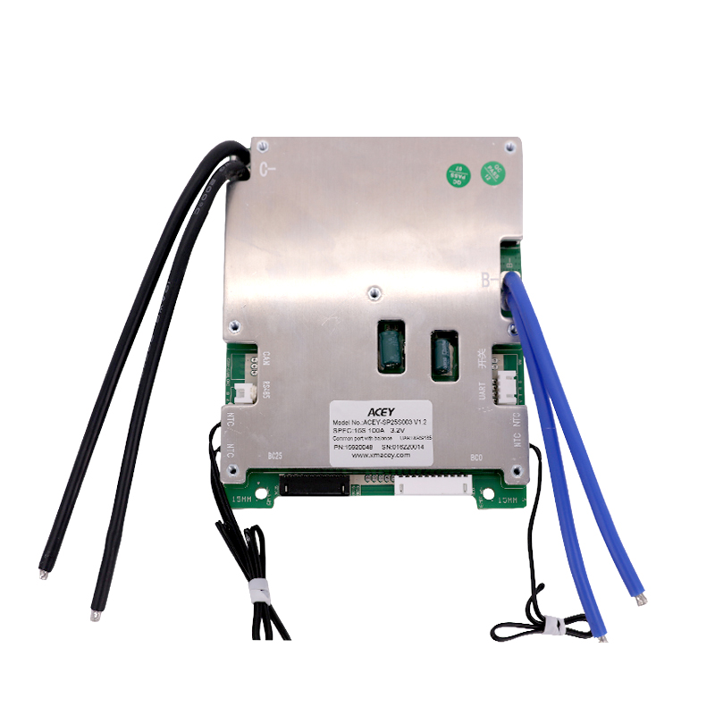
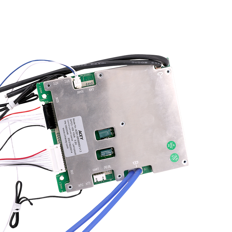
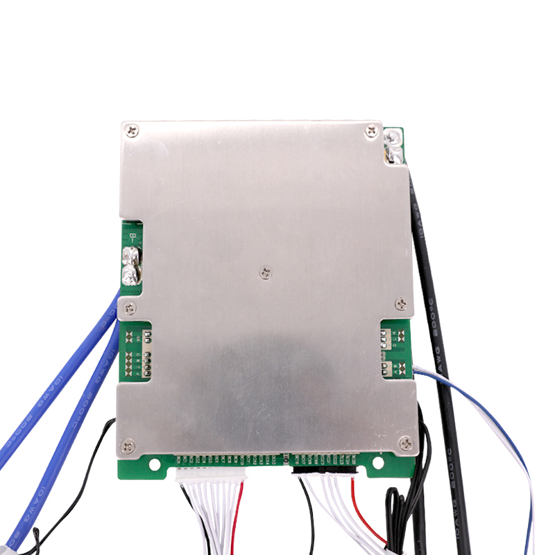
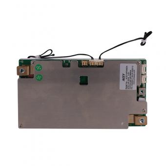
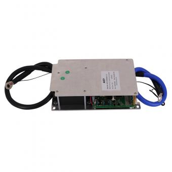
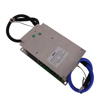
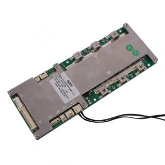
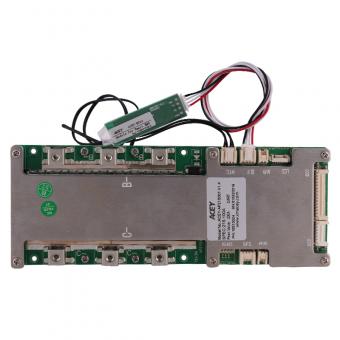
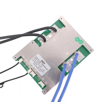
7days16s 100A 48V BMS For Lifepo4 Battery With URAT RS485 Canbus Communication
Product Introduction
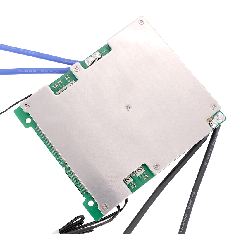
ACEY-SP25S003 is designed by Xiamen Acey New Energy Technology Co., Ltd. It is an intelligent protection board scheme specially designed for 7-25 series battery packs of start-up battery and electric energy storage products.It is suitable for lithium batteries with different chemical properties, such as lithium ion, lithium polymer, lithium iron phosphate, etc.The protection board has strong load carrying capacity and the maximum continuous discharge current can reach 100A.
● 7-25cell series protection
● Various protection functions for charging and discharging
● Discharge over current, short circuit protection functional processes of hardware
● Discharge control switch and predischarge function
● Over voltage, under voltage, temperature and overload protection function processing of software
● Accurate SOC calculation with automatic SOC learning function
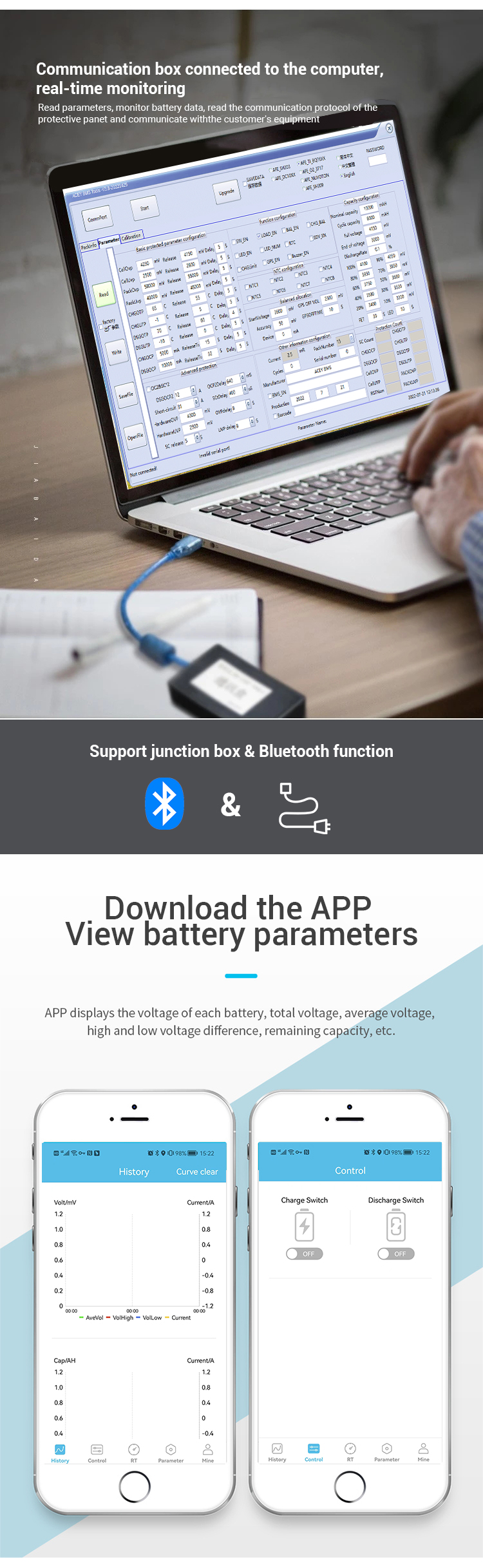
● RS485 communication function can read all battery data in real time and upgrade online.
● RS485 and UART can work simultaneously.
Electrical Characteristics
| Functions | Test items | specification | Unit | ||
| Min. | Type | Max. | |||
| Operating Voltage | voltage range | 60 | 84 | V | |
| Operating current | recharging current | -- | -- | 100 | A |
| Discharging current | -- | -- | 100 | A | |
| Charging protection | Charger voltage (CC -CV) | 83 | V | ||
| Over-charge protection voltage | 4.15 | 4.2 | 4.25 | V | |
| Over-charge protection delay time | 1000 | 2000 | 3000 | M S | |
| Over-charge protection recovery voltage | 4.05 | 4.1 | 4.15 | V | |
| Discharge protection | Over-discharge protection voltage | 2.9 | 3 | 3.1 | V |
| Over-discharge protection delay time | 1000 | 2000 | 3000 | M S | |
| Over-discharge protection recovery voltage | 2.1 | 3.2 | 3.3 | V | |
| Equalization function | Balanced turn-on voltage | 3.95 | 4 | 4.05 | V |
| Balanced turn-on voltage difference | 15 | M V | |||
| Equilibrium mode | Charge equalization | ||||
| Equilibrium current | 40 | 60 | M A | ||
| Over current protection | Charging over current protection value | 35 | 40 | 45 | A |
| Charging over current delay | 7 | 10 | 13 | S | |
| charge over current protection recovery condition | Delay 32S release | ||||
| Discharge over current 1 protection current value | 115 | 120 | 125 | A | |
| Discharge over current 1 protection delay | 7 | 10 | 13 | S | |
| Discharge over current 2 protection current value | 350 | 430 | A | ||
| Discharge over current 2 protection delay | 200 | 700 | M S | ||
| Discharge over current protection recovery condition | Delay 32S release | ||||
| Temperature protection | High temperature protection value of charging | 48 | 50 | 52 | ℃ |
| Release value of charging high temperature protection | 43 | 45 | 47 | ℃ | |
| Low temperature protection value of charging | -7 | -5 | -3 | ℃ | |
| Charging low temperature protection release value | -2 | 0 | 2 | ℃ | |
| High temperature protection value of discharge | 63 | 65 | 67 | ℃ | |
| Release value of discharging high temperature protection | 53 | 55 | 57 | ℃ | |
| Low temperature protection value of discharging | -12 | -10 | -8 | ℃ | |
| Discharging low temperature protection release value | -2 | 0 | 2 | ℃ | |
| Short circuit protection | Short circuit protection delay time | 200 | 600 | U S | |
| Short circuit protection recovery | Charge recovery \ Disconnect load delay 5S | ||||
| Internal resistance | Discharge loop internal resistance | / | 5 | 10 | M R |
| Self-consuming | Operating mode | 20 | M A | ||
| Sleep mode | 300 | U A | |||
| Sleep condition and delay | No current \ communication \ Delay of 10S under protection state | ||||
| Operating temperature | Normal working range | -20 | 70 | ℃ | |
| storage temperature | Humidity is lower than 90%, | -40 | 85 | ℃ | |
| Protection board size | length*Width*Height | MAX: 145*120*18 | mm | ||
Software parameter description
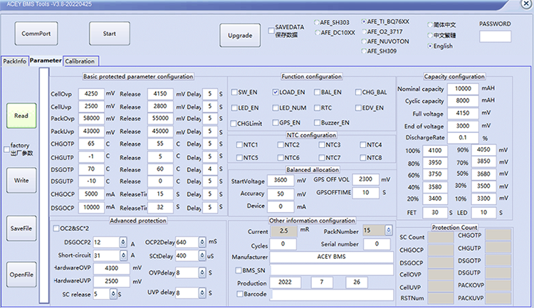
Protection function description:
Overcharge protection: When the battery is under the charging state, the voltage keeps going up. When the protection board detects that the voltage of any cell is higher than the overcharge protection value, the protection board will start timing immediately. When the time reaches the overcharge protection delay, the protection board will turn off the charging MOS tube, at that time, it cannot be charged.
Overcharge protection recovery: After the overvoltage protection appears on the protection board, the battery voltage will going down under the static or discharge state of the battery. When the protection board detects that each voltage is lower than the recovery voltage of the overcharge protection, the protection board will output a signal and turn on the charging MOS tube to charge.
Over-discharge protection: When the battery is under the discharge state, the voltage keeps going down. When the protection board detects that the voltage of any cell is lower than the overcharge protection value, the protection board will start timing immediately. When the time reaches the over discharge protection delay, the output signal of the protection board will turn off the discharge MOS tube, the load lock circuit will work, but, it cannot discharge at this time.
Over discharge protection recovery: After the over discharge protection appears on the protection board, the battery voltage will going up under the static or discharge state of the battery. When the protection board detects that each voltage is higher than the recovery voltage of the over discharge protection. At this time, disconnect the load or charge, the protection board will output a signal and turn on the charging MOS tube to charge.
Overcurrent protection: When the battery is under the static or discharge state, the current suddenly increases. When the protection board detects that the current reaches the overcurrent protection value, the protection board will start timing at that time. When the current duration in the circuit reaches the overcurrent protection delay time, the output signal of the protection board will turn off the discharge MOS tube, and the load lock circuit will work. At this time, the discharge cannot be conducted.
Overcurrent protection recovery: After the discharge overcurrent protection appears on the protection board, the discharge MOS tube is turned off, and the current in the loop becomes 0. At this time, the load is disconnected or charged, the output signal of the protection board will turn on the discharge MOS tube to discharge.
Product Display


 4s Lifepo4 12v 200a Smart Bms With UART/RS485 And Heating Function
ACEY-SP04S034 is a software protection board scheme specially designed for 3~4 strings of lithium battery packs.
 7S-20S 200A 300A 3.2V Lifepo4 Smart BMS With UART RS485
ACEY-AP20S006-LFP is a software protection board scheme specially designed for 7~20 strings of lithium battery packs.
 7S 20S 3.7V 200A 300A NMC Smart BMS With Balance UART RS485
【ACEY-AP20S006-NMC】7~20 strings of Lithium Iron Battery
 6S-21S 3.2V 100A 200A Software Lifepo4 Smart BMS With UART
ACEY-AP21S001 is specially designed for 6~21 strings of lithium battery packs.
 21S 3.7V 100A 200A NMC Smart BMS Manufacturers With UART
【ACEY-AP21S001】6s-21s 100A~200A NMC Smart BMS with UART.
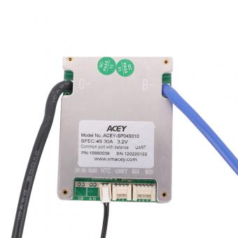 4S 30A Smart Wireless Lifepo4 Bms With UART RS485 Communication
ACEY-SP04S010 is an intelligent protection board scheme specially designed for 3 ~ 4 series battery packs of power tools, 12V starting power supply, medical batteries and other products.
 4S 80A 3.2v Lifepo4 Smart Bms 12v Protection Board with UART and RS485
【ACEY-SP04S020】4S 80A 12v lifepo4 battery pack smart bms protection board with UART and RS485 for electric motor
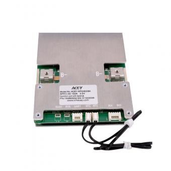 150a 12v 4s Protection Circuit Board With UART and RS485 for Lifepo4 Battery
【ACEY-SP04S028A】4S 150A 12V battery management system smart bms for lifepo4 battery with UART and RS485.
703, 7F, Zhonghengji Building, No.223, Qishan North Road, Huli District, Xiamen, Fujian, China
Email : allen@xmacey.com
Tel : +8618950009155
Whatsapp : +8618950009155