Battery Pack Assembly Process Series 4 – Semi-Finished Product Assembly
A power battery system can be metaphorically compared to an "army" that needs to operate continuously for 5–10 years, with each component playing a distinct role and function:
-
Battery Cells: Like soldiers in a combat unit (basic mission: store and release electrical energy), they serve as the foundation of the army.
-
Battery Management System (BMS): Acts as the command center, responsible for receiving instructions, collecting data, making decisions, issuing commands, and providing protection.
-
Thermal Management System: Functions as the logistical support system, responsible for heating or cooling to maintain the battery’s optimal operational state.
-
Sensors: Serve as scouts, gathering critical information.
-
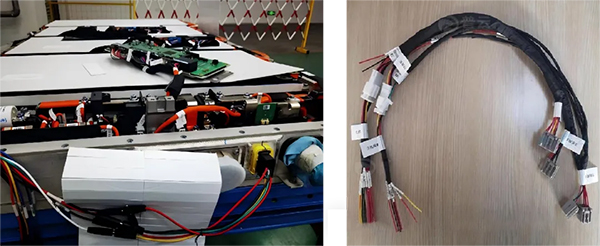
Wiring Harnesses and Connectors: Act as the communication and transportation network, facilitating information transfer and power delivery.
-
Other Components: Similar to various supplies—though not primary, they significantly impact system performance.
Semi-finished product assembly involves integrating all these departments, supplies, communication, and transportation systems into a cohesive and combat-ready "army".
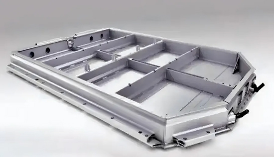
01 Box Pre-Treatment
Currently, battery pack boxes are mostly made of extruded aluminum alloy profiles, which are first machined and then spliced by CMT welding, argon arc welding, stir friction welding (FSW), laser welding and other welding methods.
The inside of the box generally needs to be sprayed with insulating powder to eliminate potential leakage risks. The bottom of the box is generally evenly sprayed with foamed polyurethane to protect the liquid cooling plate and also play a certain role in heat preservation.
The box needs to undergo strict cleaning and air tightness inspection. The supplier should conduct a full inspection of the box before delivery to ensure that the air tightness is qualified before delivery.
Pre-treatment of the box generally includes:
-
Installation and fixation of high/low-voltage plug-ins (positive and negative fast plug-ins, low-voltage communication fast plug-ins)
-
Fixation of busbar
-
Pasting of module limit pads (to prevent direct contact between the battery cell and the box liquid cooling plate)
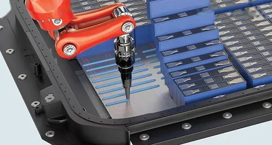
02 Gluing
Gluing is a key step in battery pack assembly, mainly used to achieve sealing, fixation and heat conduction between the box and the module, and between the modules.
Sealant is mainly used between the box and the module to prevent moisture, dust and other external impurities from entering the box and ensure the stability of the internal environment of the battery pack.
Since there is a certain gap between the module and the liquid cooling plate or heating film, a layer of thermal conductive glue is added between the two to connect them, which not only enhances the overall structural strength of the battery pack, but also improves the efficiency of heat dissipation of the battery cell.
Thermal conductive glue: Generally, it consists of two components, A and B:
-
Glue A is the main performance glue
-
Glue B is to help A glue solidify.
In the actual factory production process, in order to speed up the production rhythm, a glue machine is generally used to spray thermal conductive glue. In special circumstances, pneumatic glue guns can also be used for manual spraying.
Thermal conductive glue that only plays a heat-conducting role generally has a lower viscosity, while thermal conductive structural glue has a stronger viscosity, which has both heat-conducting and certain fixing effects.
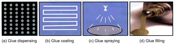
Gluing methods: glue dispensing, glue coating, glue spraying and glue filling.
-
Glue dispensing: mainly used for wiring harness fixation and preventing welding oxidation
-
Glue coating: mainly used for fixation between battery cells, or heat conduction between battery cells and box body
-
Spraying glue: mainly used for fixation and heat conduction at the bottom of the box body (mostly used for non-module solutions)
03 Module Hoisting Into The Box
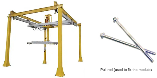
After the module is welded, it needs to be clamped and fixed by tooling, and then hoisted into the designated position in the box body. The hoisting tooling is generally specially developed, and the clamping force should be moderate, which should ensure the stability of the module without causing damage to the module. The tooling should ensure that the module will not shake or fall off during the hoisting process.
After entering the box, the module end plate is fixed to the mounting hole on the box beam by a pull rod (a non-standard long bolt). After that, a layer of insulating sheet needs to be fixed on the integrated cover to prevent personnel from directly contacting the high-voltage pole piece.
04 Plug-in Panel and BMS Installation
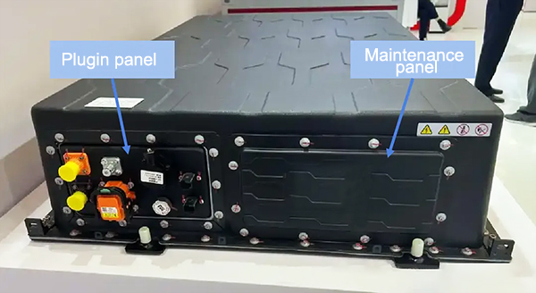
After the module is hoisted into the box, it is necessary to install BMS and various connectors. General connectors include: high-voltage plug-ins, low-voltage plug-ins, fire hydrants, explosion-proof valves, MSD (maintenance switches), etc. At present, the design scheme adopted by major pack integrators is to integrate these plug-ins on a plug-in panel.
This design can simplify the installation process and speed up the production cycle during the manufacturing process. In addition, the battery box cover only needs to open the panel installation hole, instead of opening the installation hole for each plug-in.
Some battery packs may also have a panel, which is the maintenance panel, because the BMS is more likely to fail during the long-term operation of the battery pack. The BMS can be removed from the battery pack through the maintenance panel without removing the entire battery box cover, which is very troublesome, and frequent removal of the box cover may affect the airtightness of the battery pack, resulting in a decrease in the IP protection level.
05 Installation Of Serial Copper Busbars And Communication Harnesses
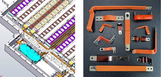
Battery packs are now basically "module-free designs". The serial and parallel connection between cells is achieved through CCS (integrated busbars), while the serial and parallel connection between modules is connected through copper busbars.
Copper busbars are divided into soft and hard types. Soft copper busbars are made by laminating multiple layers of copper foil, polymer diffusion welding, and heat shrink film. Soft copper busbars can be bent, are more flexible, easy to install, and have better vibration resistance, but are more expensive than hard copper busbars. Hard copper busbars are made by cutting, bending, and heat shrink film of T2 copper.
It is worth noting that longer copper busbars need to be fixed on the module end plate or box, generally fixed with plastic buckles, or directly pasted with foam adhesive.
Although the current battery pack structure has been greatly simplified, the communication between CCS and BMS still needs to be achieved through low-voltage harnesses. The temperature and voltage sensors on the CCS are responsible for collecting signals, and the communication harness is responsible for transmitting data between the BMS and CCS.
In order to ensure the stability of signal transmission, shielding and insulation treatment of communication wiring harnesses are crucial, which can effectively prevent the influence of external electromagnetic interference on the signal.